This last drawing was one out of a new textbook, Mechanical Drawing: Board and CAD Techniques. It was a 4-part drawing of a depth gauge, including a base, a knurled screw, a depth rod, and a handle. It was a pretty easy drawing, but I did get to learn some new things in inventor while drawing it. Below are drawings of the depth gauge:
Welcome
This is my blog for my engineering classes.
Thursday, August 30, 2012
Monday, August 27, 2012
The Weldment Unit
This first unit in Technical Manufacturing was a fun and semi-easy one. I'm two weeks into school and I know all about weldments now. I drew several weldment drawings and added weldment symbols to them, as well as the standard dimensions. This unit also took me back to AutoCAD, which I hadn't used in about a year. Some of my assignments are pictured below:
Tuesday, May 15, 2012
The Carburetor
This last project was to draw a carburetor. Some parts were easy, but others were challenging, like ones that had irregular shapes. The animation proposed a challenge, because it was originally cutting out a part of the movement due to the floor being too high. Each part was individually drawn, and in the end, they all fit together greatly.
Monday, April 16, 2012
The Gear Transmission
This last project was drawing a gear transmission in Inventor. The assembly consists of three gears, two lock gears, an axis, and several washers and retaining rings, for a total of thirteen parts. It was easier to animate that past projects, and the hardest part was drawing the gears, as the prongs varied in depth, and the measuring was dificult in some cases. The overall project was more time consuming than difficult. But in the end, the drawn part looks very cool and just like its real counterpart.
 |
| The Gear Transmission |
Friday, March 23, 2012
The C Clamp
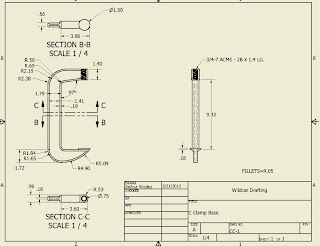
My latest project was a c clamp. Its size initially made it hard to dimension, as it was larger than my regular measuring tool reached. It's shape confused me for a while, but after looking at it and applying some dimensions, my Inventor replication was really close to the actual piece. The hardest part though was definitely animating it. I knew what to do, but I couldn't get inventor to move the right parts in the right way. I eventually decided to play constraints between parts to my advantage and move only one part, dragging the other parts with it.
Thursday, March 15, 2012
Making Digital Plastics
In this last project, I took a plastic Wheelr High School water bottle and drew it in Inventor. The drawings I had to make with it followed the sameoutline as the Bottle Opener, but some parts presented a challenge. I couldn't remove the tip of the lid, so I had to measure around the lid base to measure it. Also, the lid and its features were new and irregular to me. The bottle, though it's the largest part, was probably the easiest.
 |
| Bottle Base |
 |
| Bottle Exploded Isometric |
 |
| Bottle Lid Tip |
 |
| Bottle Section |
 |
| Bottle Lid |
 |
| Inventor Studio Bottle |
Monday, March 5, 2012
Special Project #1
Since the last post, I have spent around two weeks measuring and drawing a bottle opener/cork remover in inventor. It was interesting to get every detail in, because some had to be done in a specific order in order for the part to turn out right, and then one part I spent less than two total minutes on. In the end, the parts fit together perfectly, and I animated the bottle opener to do what it does in the physical world.
 |
| Bottle Opener Base |
 |
| Bottle Opener Coil Screw |
 |
| Bottle Opener Pin |
 |
| Bottle Opener Exploded Isometric |
 |
| Bottle Opener Lifting Gear Lever |
 |
| Bottle Opener Assembly Section |
 |
| Bottle Opener Presentation |
Subscribe to:
Posts (Atom)


.bmp)
.bmp)
.bmp)
.bmp)
.bmp)
.bmp)
.bmp)
.bmp)
.bmp)
.bmp)
.bmp)


